Guides
Helpful
Hints

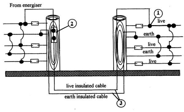
Earth Wire Return System
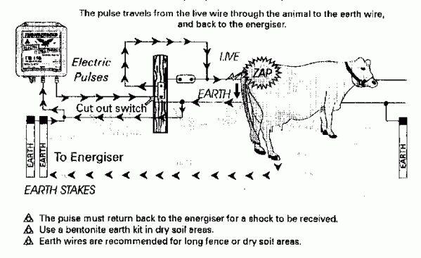
Ground Earth Return System

Earthing
- Drive 3 stakes into the ground 1.5m
- Space stakes 5m apart
- Use non corrosive stakes, eg galvanised steel
- Position earth stakes in a moist area. They must be 10m away from other earth systems
- Additional earth wire stakes (A) are required every 1.5km of fence run.
- Connect to earth return wires using joint clamps
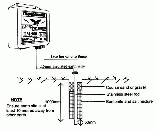
In dry soil areas use Thunderbird Super Earth Kits (Bentonite)
Kit Contents
- 1 Stainless steel rod
- 1 Stainless steel earth clamp
- 4kg (approx) bentonite
- 2kg (approx) salt
Installation Instructions
- Auger a hole 1 metre deep and 100mm (4″) in diameter in moist area
- Place stainless steel rod in center of hole and drive 50mm into ground
- Mix bentonite and salt and pour mixture into hole around rod
- Top up hole with coarse sand or gravel. Water well
- Connect s/steel rod to energiser and test earth. If inadequate install another earth kit 10 metres away.
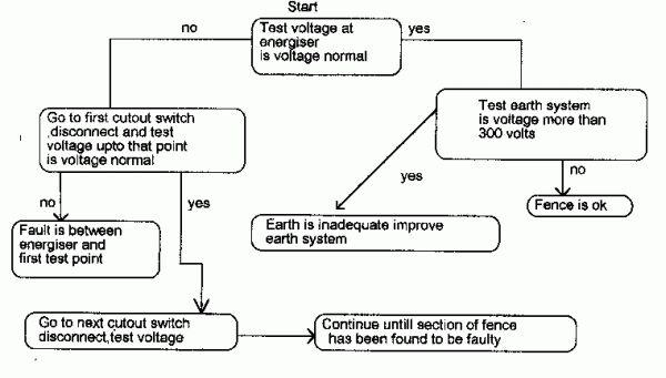
Fault Finding
Faults could be caused by shorts, vegetation, poor joints, faulty insulation, extension of fence line over the energiser capacity
Recommended: Run earth wires parallel to live wires and use Thunderbird Super Earth Kits (Bentonite).

Fence Layout
Careful planning will prove wothwhile for the future, reducing input time and maintenance.
Short Runs
It is best to have several short runs from the energiser. The pulse does not have to travel as far and retains good voltage.
Laneways
Laneways between paddocks are recomended. This allows quick and easy movement of stock.
Paddocks
Square paddocks provide more even grazing and less waste caused by animal traffic. The number of paddocks can be important during periods of low pasture growth. A large number of paddocks provide a longer rotation period.
Floodways
Various designs of floodgates can be used. Below are two systems that are effective.
All floodgates should incorporate a flood/short isolator. This stops the main fence shorting out when water contacts the lower part of the fence.
Hanging wire of chain etc. should be 150mm – 200mm above the normal water level
Vegetation
Flood/short isolators can be used between the bottom and the above live wires. When green grass etc. touches the bottom wire, the above wires do not lose power.
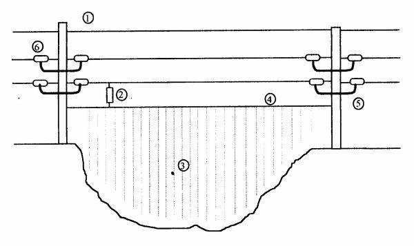
Legend
- Earth wire – also takes fence strain over creek.
- Flood isolator – supplies pulses to mesh panels.
- Mesh panels or hanging wires or chains.
- Heavy support cable – insulated both ends
- Underground cable or insulated cable.
- Insulator
Gateways
Underground cable (3) is buried a minimum of 300mm below the surface inside poly pipe. Bend the ends of the pipe downwards to avoid rainwater entry. Joint clamps (1) are used for all wire connections or joints. Cut switch (2) is best installed on the energiser side of the gateway for isolation.
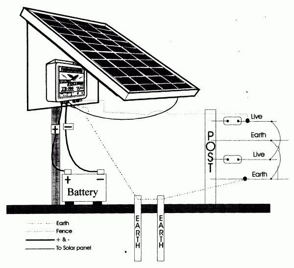
Solar Powered Energisers
Position mounting post(s) securely into ground (concrete if possible) in an area free of shading or possible mechanical damage, near the middle of the fence line. Use galvanised or 8′ steel star post (galvanised is recommended).
Carefully mount solar panel and frame to post(s), tighten U-bolt securely. Face panels to the equator (face panel north if in southern hemisphere).
Connect solar panels + (red) to energisers (+) then connect solar panel – (black) to energiser (-) terminals. Then connect battery leads + (red) energiser (+) and connect – (black) to energiser (-) terminals.
Connect energiser to the earth system and insulated fence.
Radio Interference
Thunderbird energisers have radio interference suppression circuitry, however, problems can still occur from a number of causes.
Fault Finding Flow Chart
To start disconnect the energiser from the earth and fence.
Turn energiser ON
Does the Radio Click?
YES
The problem is the earth or fence line.
- Make sure no loose connections are present on mains plugs and sockets of energiser or radio.
- Earth Radio and provide a better aerial to the radio.
- The mains power supply earth needs to be adequate.
No
The problem is the mains power supply or the energiser.
- Improve energiser’s earth (see earth testing data sheets).
- Be sure the energiser’s earth is 10 metres away from the mains power earth.
- Make sure energiser’s earth or earth wire is not in contact with a large amount of metal above the ground.
- All connections must be clamped tight on live and earth wires and have good connections to eliminate arcing.
- Do not run live wires along or close to phone lines.
- Check for arcing insulators or other arcs.
Safety Requirements
- Only one energiser may be connected to a fence.
- Barbed wire MUST NOT be electrified.
- Energisers should, if possible, be installed inside a building in a position free from the risk of mechanical damage. If mounted outdoors, they should be mounted on a substantial structure in a position free from mechanical damage.
- Each energiser should be connected to a separate earthing peg, at least 10 metres away from any other earthing device.
- Fence lines crossing beneath overhead power lines should be avoided wherever possible. If such a crossing cannot be avoided, it should be made underneath the power lines and as nearly as possible at right angles to it.
If an electric fence has to be installed in the vicinity of an overhead power line, the vertical distance between any fence wire or connecting lead and surface of the earth should not exceed 2 metres. - Fence wiring should be so installed that it is well away from telephone or telegraph line or radio aerials.
- An electric fence, when installed in such a position that members of the public might reasonably be expected to touch it, should be identified by suitable signs clamped to conductor or fastened to the post at intervals at regular intervals. The signs should have a size of 200mm x 100mm. The inscription on the sign should take the form of either the symbol below of the words “ELECTRIC FENCE”. Any lettering should have a height of at least 25mm. It is recommended that the basic colour of the sign be yellow inscription.
- Where the energiser is to supply a system of conductors used for detering birds from roosting on buildings, no conductor should be connected to earth. A switch should be installed to provide a means of isolating the controller from all poles of the supply and clear warning notices should be fitted at every point where persons may have ready access to the conductors. The notice shall be the same as that described in No. 7 (above).
- In Bush Fire high risk times, it is advisable to power the energiser from the low power terminals or switch the unit off.
- DO NOT store flammable goods near an electric fence because if a fault is present a spark can be produced.

Strip Grazing
Get the most out of your crops and pastures
Benefits of Strip Grazing
- Higher producing pastures
- Higher stock rates
- No more stock camps
- Reducing worm infestation
- Faster pasture regrowth
Important
- Poly tape and poly wire are only recommended for short runs, for longer runs use 1.6mm gal wire.
- Always be sure to have a portable, moveable livestock water supply.
- Back fence the previously grazed area for early grass regrowth.
Training Livestock
In order for animals to realise the fence line represents a shocking jolt, they need to discover an electric fence in their own time in a holding paddock for several days. If done correctly, animals will respect an electric fence and stay clear of it. Use offset wires, install the fence around the height of the animal’s nose and earth the non insulated wires to earth stake system.
Helpful Points
- Use a large energiser in order to produce a powerful shock.
- Allow plenty of room for horses and deer to run.
- Allow time before taking out of holding paddock.
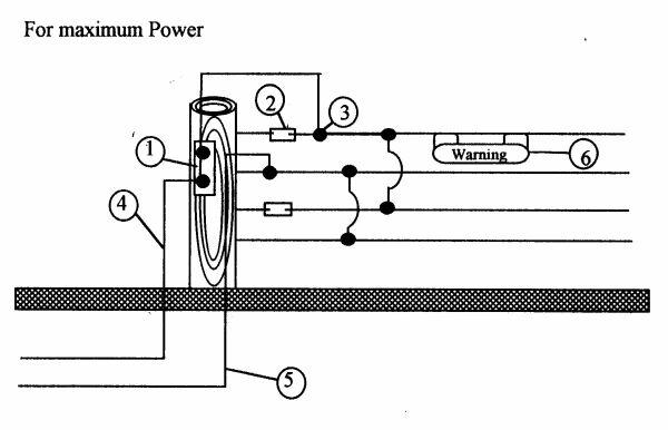
Wire Connections
- Cut out switch
- End strain insulator
- Wire joint clamp
- Underground live leadout wire
- Underground earth leadout wire
- Electric fence warning sign
To reduce voltage loss parallel all wires by joining live wires together as well as all earth wires together, at each end of the strain.
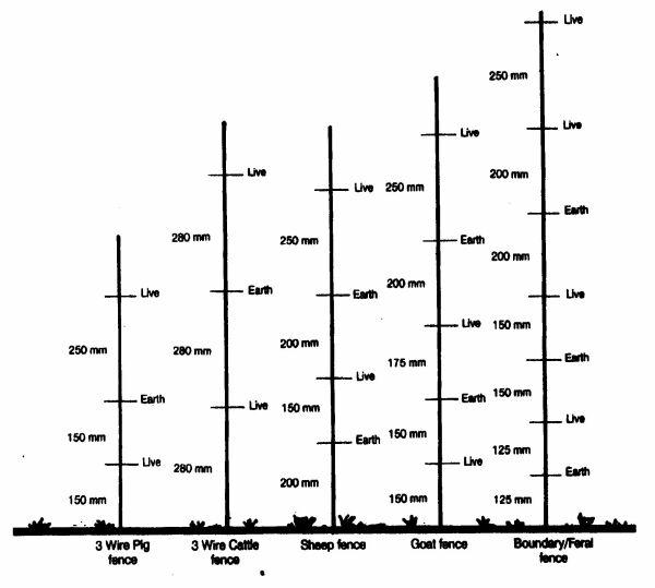
Wire Spacing
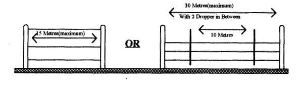
Post Spacing
The post spaces can vary on the type of country and number of fence wires used. The concept is to keep the wires the same distance apart from each other and the ground to avoid shorts.